Wednesday, August 31, 2011

Soldering Party!

The next step for the Museum Without Walls project was building the 20 Refresh Rate modules and I quickly found that hand soldering all of them would be very time consuming. So I did what any reasonable person would do and drafted my friends to help. It turned out to be a lot of fun and we only messed up one board by soldering a chip in backwards (the culprit will remained unnamed). Thanks to Tom, Nick, and Sam for all coming and helping (most of the time :)). Below are pictures of our setup (we used a fan pointing backwards for "fume extraction" though it was more "fume displacement") and the box full of the finished boards.


Sunday, August 14, 2011

PCBs Have Arrived!

It has been a while since I updated my blog but in that time the Refresh Rate Teacher project has progressed significantly. After searching for hobbyist friendly board houses, I decided to purchase custom PCBs from Seeedstudio's Fusion PCB service. I was not disappointed. Seeedstudio has incredibly reasonable pricing for custom PCBs which is normally not the case when ordering small batches. You must order in multiples of 10 from them but their pricing makes it totally worth it. To order 10 10x10 cm boards it was a mere $25 and only $4 dollars shipping! This is incredibly cheap compared to BatchPCB which Sparkfun endorses which would cost $48.75 for just one board! Check out their website for more details. They do require that your designs be open-source but that shouldn't be an issue for most hobbyists. The only downside to their service is the long wait (~3 weeks to receive your board). When I received the boards I was very pleased with their quality. I had ordered 20 boards and was pleasantly surprised to receive 24. I have since ordered more boards from them and again received 12 instead of 10. I don't know what this is due to but it's better than being shortchanged! Below you can find the pictures.


Monday, July 4, 2011

Yard Sale

Last weekend I was driving around and stopped at a yard sale in hope of finding some cool electronics. I was not disappointed. I walked around looking at old radios and other "junk". Electronics at yard sales are often obsolete, but are great platforms for hacking and mods. I walked out with two 120 watt speakers for $3 and an old Super Cub LP RC airplane for $20.

The plane needed some quick repairs, but to my delight worked after duct-taping the nose back on. I am planning on modifying it and adding ailerons and eventually hope to make a UAV out of it using the ArduPilot platform. More on that later.

I think that any DIYer should never underestimate the value of a yard sale. After all, one man's trash is another man's treasure.

Thursday, May 26, 2011

Refresh Rate Teacher v0.2

Success! After a few quick modifications, the module worked great. Well except for the one line that I haven't yet hooked up because I am using a 7 transistor darlington array instead of an 8 transistor version. I like the feel of the module in the hand but plan on cutting the corners in the final design to reduce the risk of the user cutting their hand on a sharp edge.


It works! (Mostly.)

Above are the images of v0.2 and as you can see there has been some basic reworking done to the board. First and most importantly I had to replace my original TO-92 78L05 with the TO-220 package because my circuitry required more than 100 mA which I had overlooked. Also I designed the board to be two sided, but because I can't do through plating at home I had planned on top-soldering. This turned out to be very difficult for some components. So I gave up on that and just soldered wire-wrapping wire in place of the top traces.

With this module, I finalized the code and thankfully included an ICSP header to program the board which made life a lot easier. After I got a basic design working I wrote a Processing sketch to upload new designs to my module via the serial connection.

Schematic for v 0.2

Board for v 0.2

The next step for this project will be to order the parts for the modules and then send out the board design to be manufactured. After all of that is done, I will finalize the design for the programmer and manufacture that.

Sunday, May 8, 2011

Refresh Rate Teacher v0.1

I designed and built my first prototype of the refresh rate teacher and big surprise, it didn't work. I designed my prototype in EAGLE and printed a board out in the PCB mill in my school. The PCB mill in my school however does not through-plate the holes and vias in the boards and doesn't silk screen. This can pose an issue with having double layer boards because you have to solder both sides of the board, which can be very hard for things that don't have the pins visible on the top like headers and IC sockets. So I designed my board with this in mind and made sure to limit the amount of top traces and when I did have one I made sure it went to an accessible pin. I also made sure to design the board to be compatible with parts offered at my school so I could prototype as fast as possible.

Here are some pictures of the design:

A Google SketchUp Model of v0.1

I first made a quick mock up of the design to visualize how everything would fit and also to sell to the leaders of this museum project. I found that they were impressed with being able to see what design I had in my head and it was much more effective than me just describing it. As you can see in the design, I wanted to design a backpack device in which the LED matrix would sit on top of the circuit creating a nice handheld device. Also I will use polarized headers to make sure that users can only plug the wires in the correct way.

Schematic of version 0.1

This is where I made my big mistake in the circuit. I overlooked the fact that I was using an NPN darlington array to control the select side of my LED matrix and used them instead as if they were PNP which made the whole circuit pretty much worthless. Also you may notice that there was no ISP header to program the AVR chip and that was because I am currently using the Arduino platform and you can program just using the serial port and reset. However, this proved to be more difficult than it was worth so my next design will have an ISP header.

v0.1 PCB (Blue=bottom, Red=top)

Above is the PCB design for the board and I manually routed it to minimize the number of top traces. However I did route some top traces to the AVR chip which meant I couldn't use an IC socket which in the end was too bad because I ended up wasting an ATMEGA.


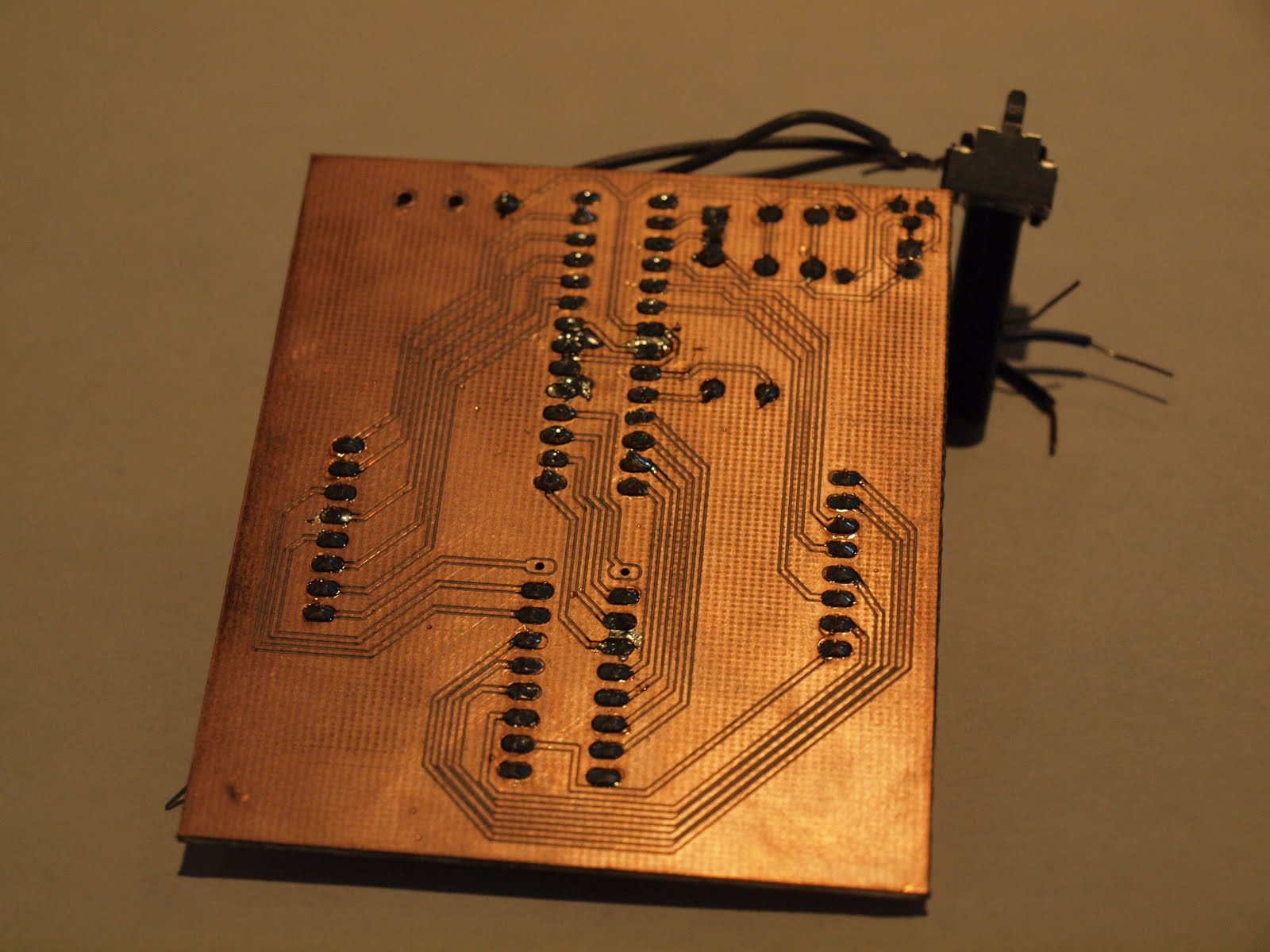
Here are some pictures of the finished prototype

I have learned several things from this prototype, one is always use an IC socket to minimize wasting expensive chips, include an ISP header especially when you are still developing the program, and always make sure you double check the datasheet of darlington arrays! I also learned a little bit more about soldering finding that all this time I had been using a solder wick incorrectly. I found that to use one effectively you place it over the solder joint you want to get rid of, heat it up, and then add a little solder to the top of the wick and then presto! the solder is gone.

Soon I will post my progress on the second prototype and hopefully I will have a video to demonstrate it.

Sunday, May 1, 2011

Refresh Rate Teacher

Currently I am working on a project for a group that is making a "museum without walls". The idea is to create mobile exhibits that can rotate around several elementary schools and educate students in science. My school is designing and building three of theses exhibits. Each exhibit has a unique theme and the exhibit I am working on is physics and engineering. There are several people involved in this exhibit and each one of us are working on a specific part to it. The idea is that a teacher will have a variety of activities they can show ranging from experiments to demos. Currently, the ideas for the things inside the exhibit are a kit to build a basic motor, a setup to demonstrate the mechanical advantages of pulleys, a setup to teach binary, and modules to demonstrate the refresh rate. I am in charge of the last project and will document in the blog my progress on it.

The idea of the project is to teach students how their TV's and computer screens work. The idea is to allow students to upload a design they make on a programming station to a module they can take to their desk. At their desk, they can adjust the refresh rate with a potentiometer and see how the display scrolls line by line and as it speeds up it looks like their image due to persistence of vision.

Currently, I am designing the modules that they take to their desks and will design the programmer in the near future. The modules are based on the Arduino and display on an 8 x 8 LED matrix. I am currently in the prototyping phase and will post my designs and pictures soon. For the programmer, I am planning to use a dual-color 8 x 8 LED so the user can highlight the LEDs and select the ones they want to turn on. The new design is uploaded to the modules using a serial connection and is loaded into its EEPROM so it can be remembered if it is reset or turned off.

Saturday, April 30, 2011

First Post

Well, this is the inaugural post of my blog and hopefully won't be the last! I hope that this blog will be a good place for me to record my projects, ideas, and experiences in electronics. I hope that this blog will be a place where others can get ideas for projects and maybe even provide some answers to other's projects. Most of all I hope this blog will last and will be enjoyable for at least a few people. Well there are a lot of things I hope for this blog and only time will tell whether it lives up to my plan for it.

(Also I hope I get better with writing my posts or else there isn't much hope for this blog :))